
PhD-Level Ultrasonic Engineering • Medical • Manufacturing • Consumer
Ultrasonic resonance depends on amplitude
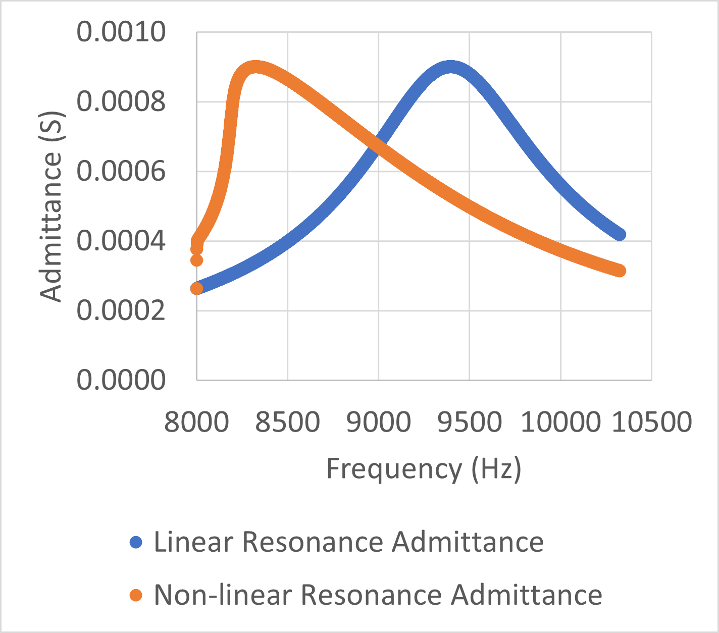
The resonance frequency in ultrasonic transducers is affected by the amplitude of power or current delivered. In the figure above, an LCR circuit's admittance is plotted for a linear LCR circuit and a non-linear LCR circuit. In the non-linear circuit, the capacitance is a function of current.
As the current increases, the capacitance increases. The result of this effect is that the resonance frequency decreases and a sharp transition is seen at the new resonance frequency.
For the plot above, the LCR values were:
- R=1110 Ohm, L =0.19 H, and C= 15.1nF.
In the nonlinear resonance, the R and L were the same, but the capacitance was defined as:
- [15.1 nF]*(1+current/0.007)^2
By using small frequency step sizes, I did not have to get fancy with the determination of current, as I could just use the current at the previous frequency step.
This representation of capacitance results in a similar maximum current amplitude to the linear model, but gives the distinct nonlinear transition and resonance frequency shift seen when doing a constant voltage sweep over the resonance frequency of an ultrasonic transducer.
For small signal excitation, the results are linear. However real-world ultrasonic transducers do not operate with "small signals", so finding appropriate analysis methods is critical for a deep analysis.